Introducing: BCIBox, an open source enclosure for the OpenBCI
The OpenBCI is a pleasantly affordable, refreshingly open source biosignal amplifier with high-quality multi-channel output, an excellent user community, and a hackable design that have made it a go-to widget for neuro-geeks from Montreal to Peru and many places in between.
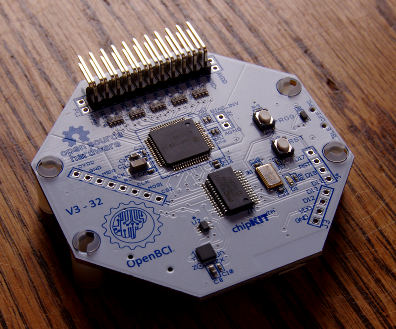
We’ve been experimenting and tinkering with the OpenBCI since its first Kickstarter release. We think it’s bellisimo, but there’s one problem: the OpenBCI comes as a bare circuit board. This is fine if you’re using the nifty Ultracortex headset, which includes a mount for the OpenBCI board. If you’re short an Ultracortex, though, or are doing other kinds of experiments like sleep tracking, EKG, EMG, EOG, or using a conventional EEG cap, the OpenBCI’s bare-board minimalism can be problematic. Once the electrodes are attached to someone’s head, it’s hard to find a safe, reliable place to put the OpenBCI and its battery pack within range of the electrode wires, and the board’s exposed circuits are vulnerable to electrostatic discharge, dust, moisture, and shorts from metallic objects or smears of conductive electrode paste. This makes storing and using the OpenBCI more challenging than ideal.
For the past year, we’ve been experimenting with a solution to this. Today we’re excited to release the BCIBox, an open source enclosure for the OpenBCI.
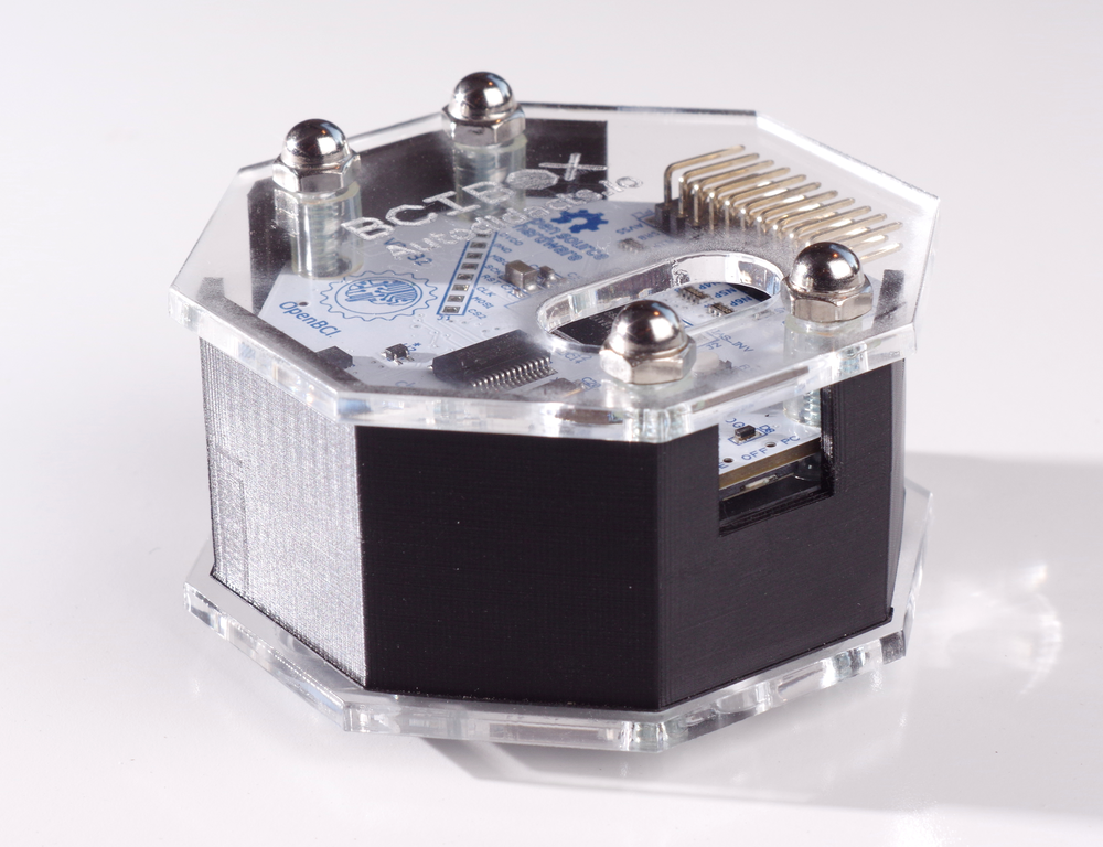
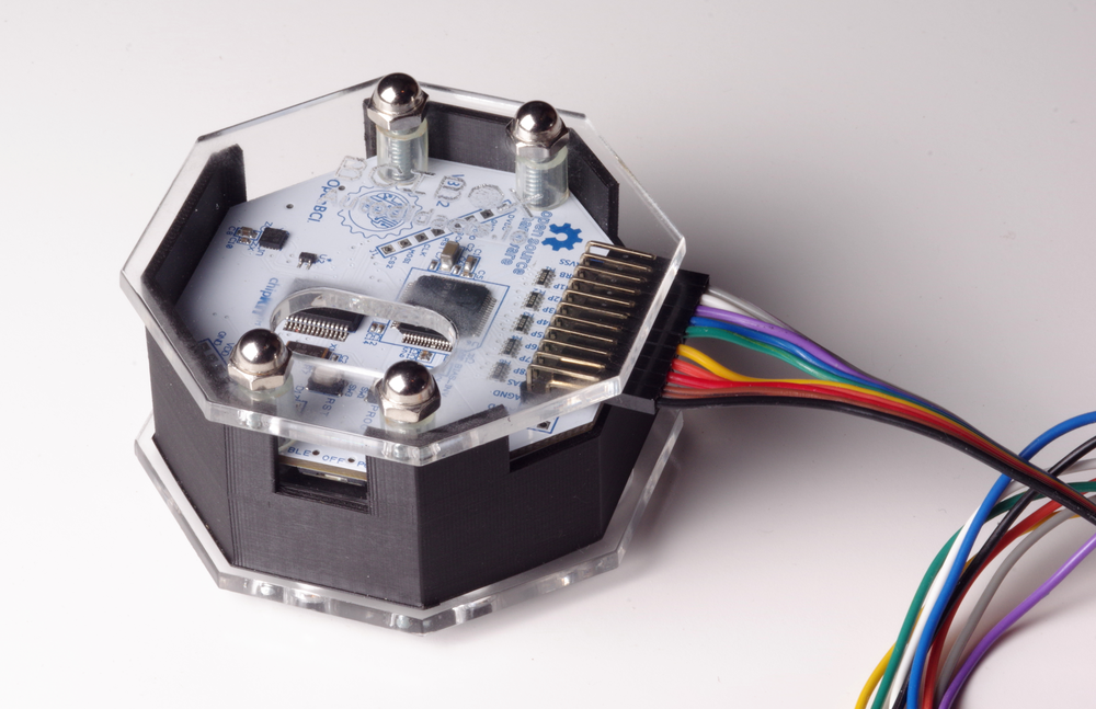
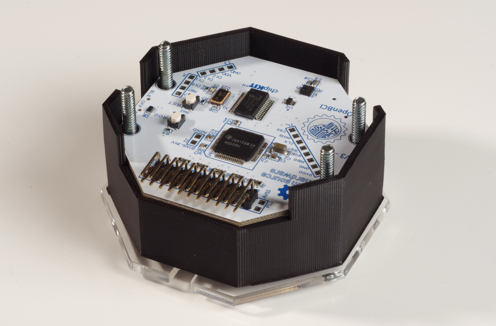
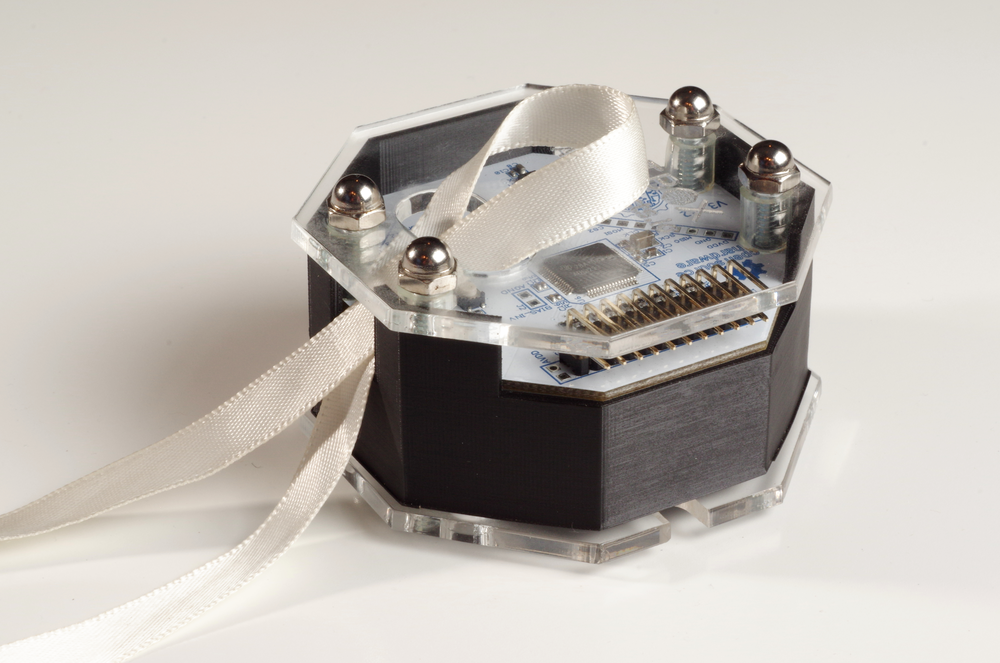
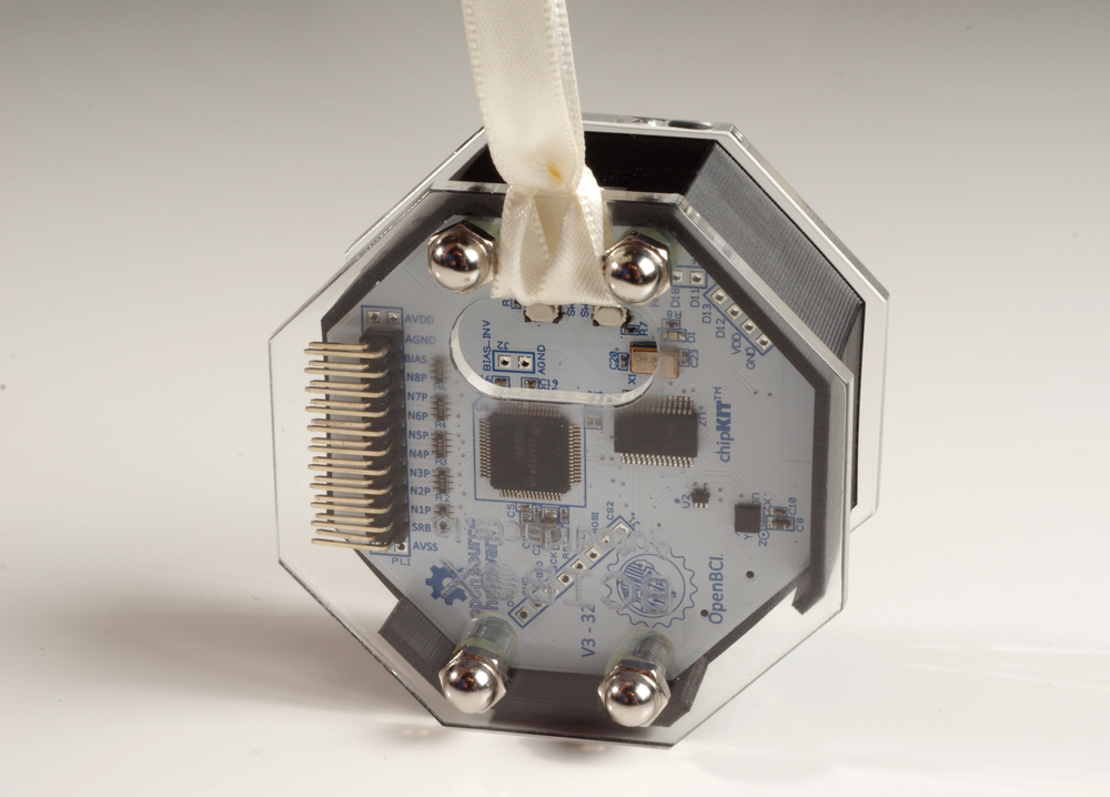
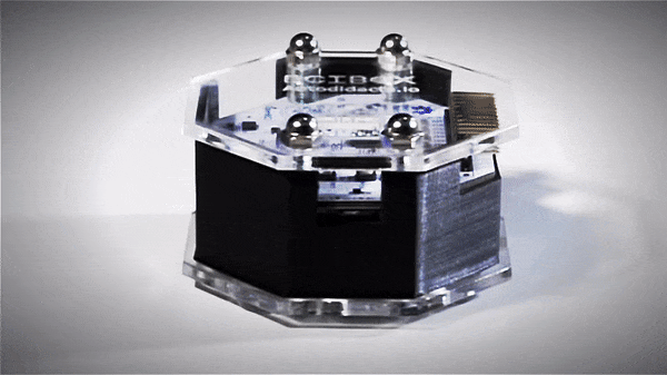
The BCIBox has a 3D-printed frame capped with top and bottom panels of laser-cut acrylic. Openings allow access to the OpenBCI’s SD card, power switch, electrode connector, and prog/reset buttons. The box fits both the original 8-bit and 32-bit OpenBCI boards and the new OpenBCI Ganglion[1].
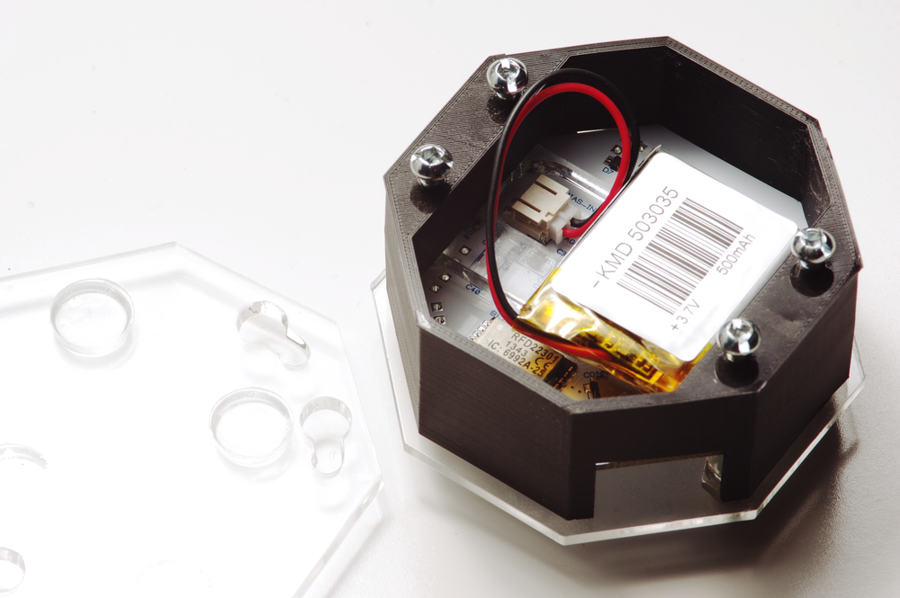
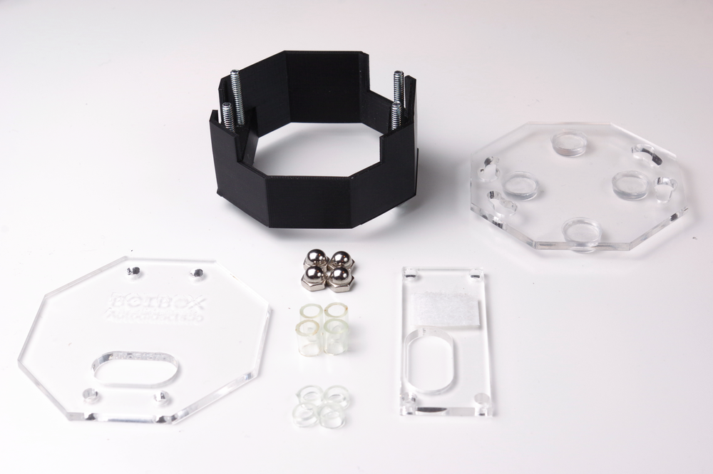
Beneath the board is a space for a velcro-attached lipo battery, and the bottom panel twists off for easy access to the battery and power connector (the box can also be used with the OpenBCI’s default AA battery pack attached beneath it, or with a lipo and boost converter inside). Neck lanyard and lapel clip attachment points help keep the BCI conveniently secured when in use.
Like the OpenBCI itself, the box is open hardware. The CAD files for printing and cutting the parts are available on GitHub, and build instructions are below. If you don’t have access to a 3D printer or laser cutter, or you’d like to save yourself the hassle of pulling together all the pieces (or you’d like to support our tinkering adventures by buying our first ever Autodidacts product!) you can purchase a complete kit with all parts included for $45.
Read on for instructions on building the BCIBox and using it with your OpenBCI.
Getting Started with the BCIBox
For DIY builders, head over to our GitHub repo to grab the CAD files for the laser cut parts and the STL files for the 3D printed components.
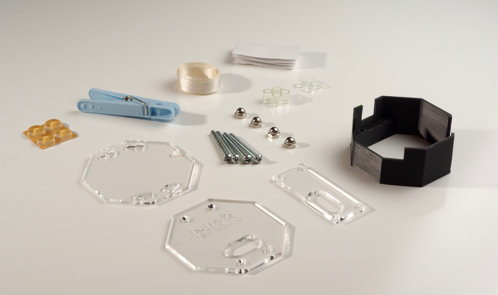
In addition to the acrylic and printed parts, you will need:
- 4 pan head machine screws (#6, 1 3/4" long)
- 4 #6 acorn nuts
- 3 inches of clear acrylic soft tubing (1/8" ID, 1/4" OD) for board standoffs
Optional parts (also included in the kit):
- Adhesive-backed rubber feet to keep the box stable and prevent it from sliding
- Adhesive-backed velcro to attach a lipo battery, AA battery pack, and lapel/pocket clip
- Lanyard string (can be used to hang the BCI around your neck if you’re short a pocket)
Printing and cutting (if you have a kit, skip these steps)
Print the sides of the enclosure
Print the enclosure sides from the STL file (BCIBox_printed_enclosure.stl). We used PLA filament, but other types should work fine as well.
Laser cut the top and bottom pieces
Laser cut the acrylic from the SVG file (BCIBox_acrylic_layout.svg). We use 1/8" acrylic for this. Other thicknesses would work, but the length of the screws would need to be adjusted accordingly.
Slice the stand-offs
Using an exacto knife or other cutting tool (some paper cutters work for this), slice off from the acrylic tube:
- 4 slices 1/8" (3 mm) long
- 4 slices 7/16" (11 mm) long
Assemble the box
Thread the four screws through the holes in the 3D printed piece, from the bottom. These screws will cut their own threads into the PLA, so it takes a bit of force to get them through the first time. Don’t screw them in all the way, but leave about a 1/4" gap between the screw heads and the PLA. Once all four screws are threaded through this far, slip the bottom acrylic piece over the screw heads, and turn it clockwise. The acrylic should click into place.
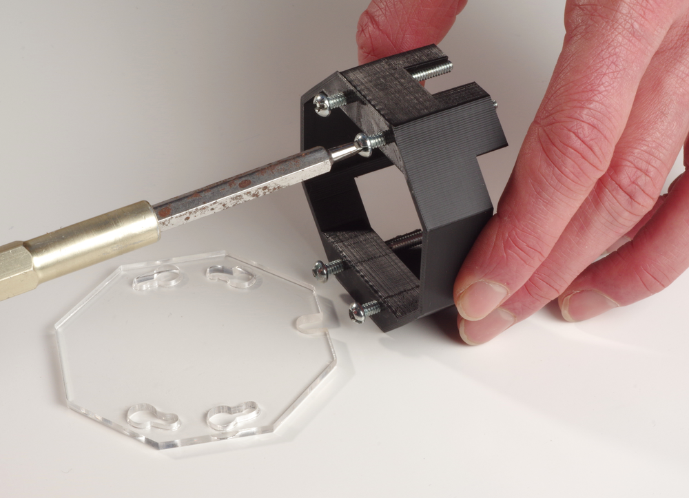
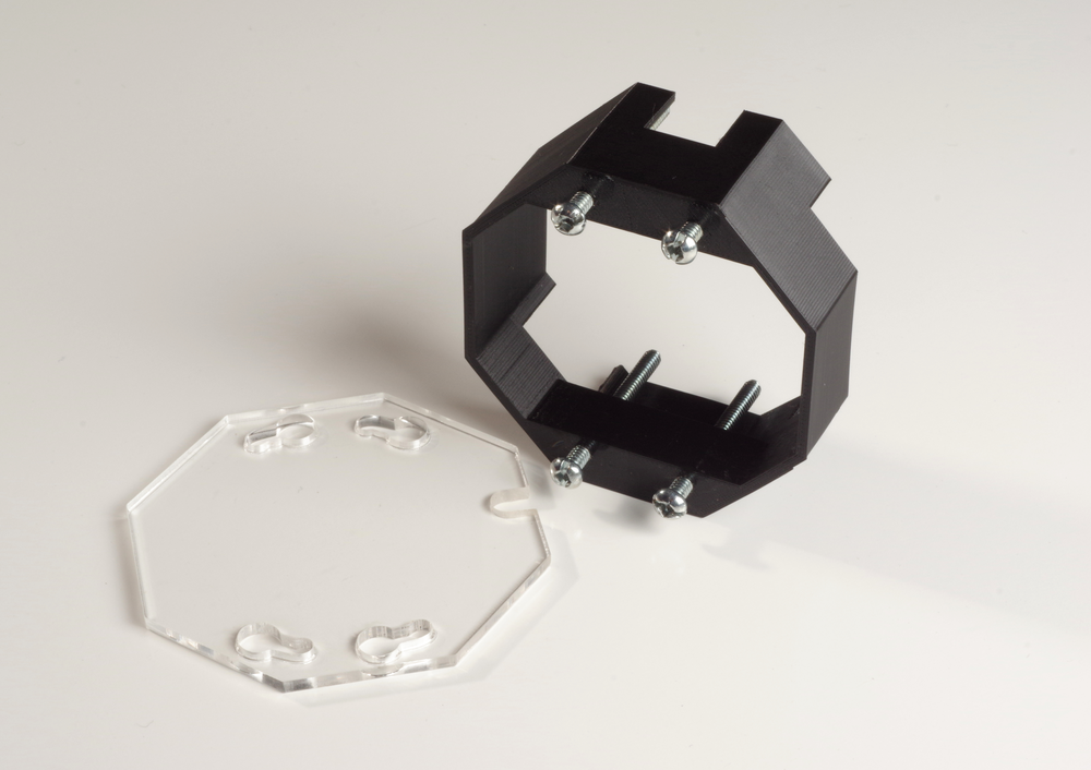
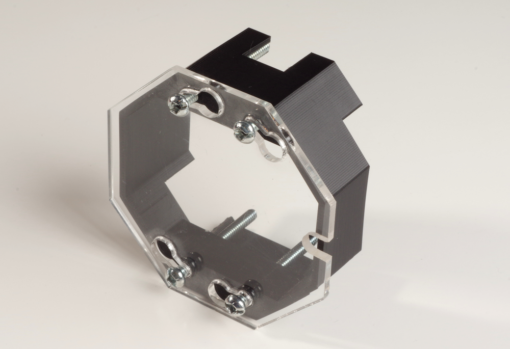
Snug the screws up to the acrylic, but don’t make them too tight. The acrylic should still be able to be removed without loosening the screws. Flip the box over so it’s upright.
Turn the BCIBox so the largest cutout in the PLA is facing toward you. Place the acrylic battery support piece onto the screws, making sure it’s oriented so that the hole for the OpenBCI power jack is to the left. Place one of the four short (1/8") acrylic tubing standoffs onto each of the screws.
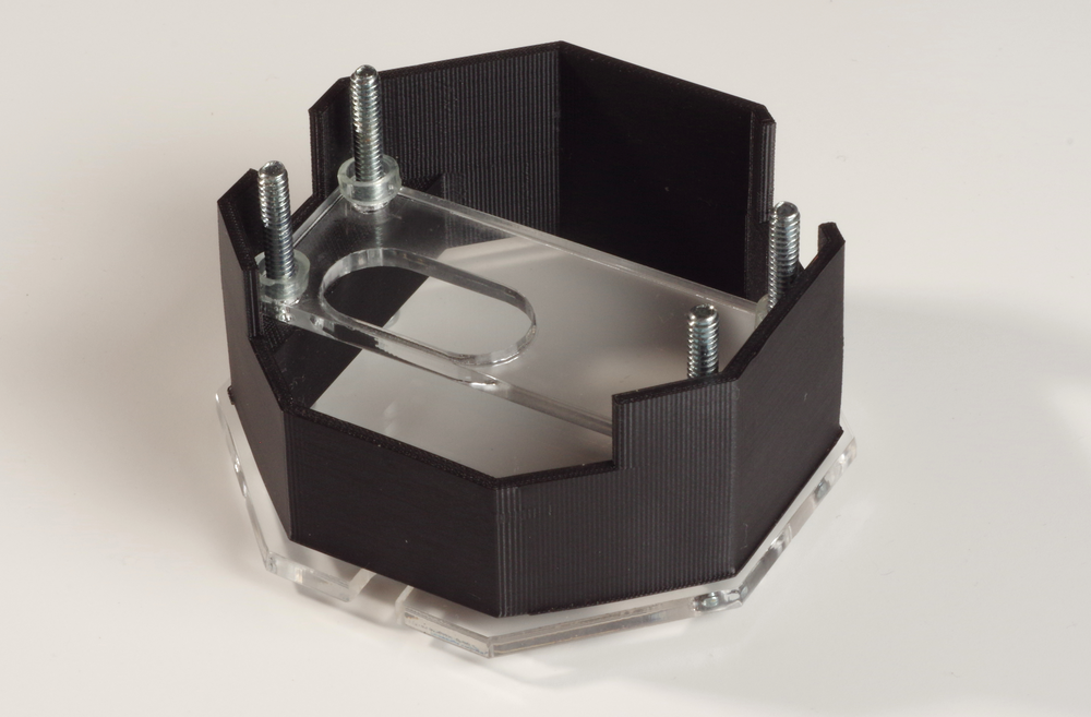
Remove the standoffs from your OpenBCI by pinching each standoff’s clip end where it protrudes from the top of the OpenBCI board. Store these in a safe spot so you can reuse them if you need to use the OpenBCI without the box in the future.
Place the OpenBCI board onto the BCIBox screws, with the electrode connector facing toward you. Put the remaining four acrylic tubing standoffs onto the screws, and then put on the top panel (oriented so the hole for button access is above the pushbuttons on the OpenBCI board). Put on the four acorn nuts and tighten them gently.
Power up!
There are two ways of powering your newly-clothed OpenBCI: the AA battery pack that comes with the OpenBCI, or a light-weight lipo pack that will fit right inside the case.
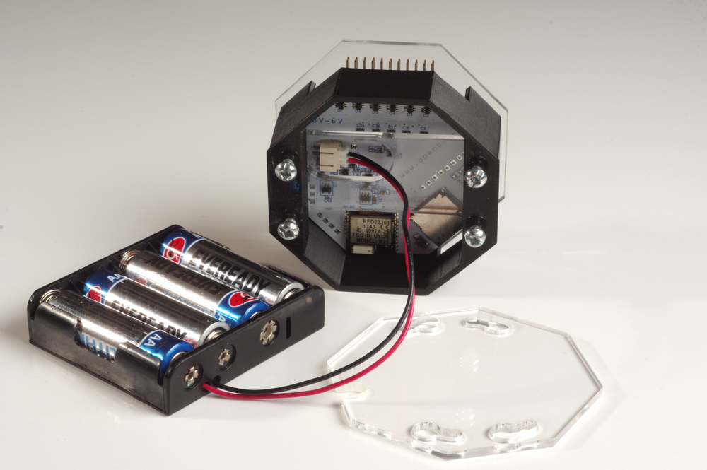
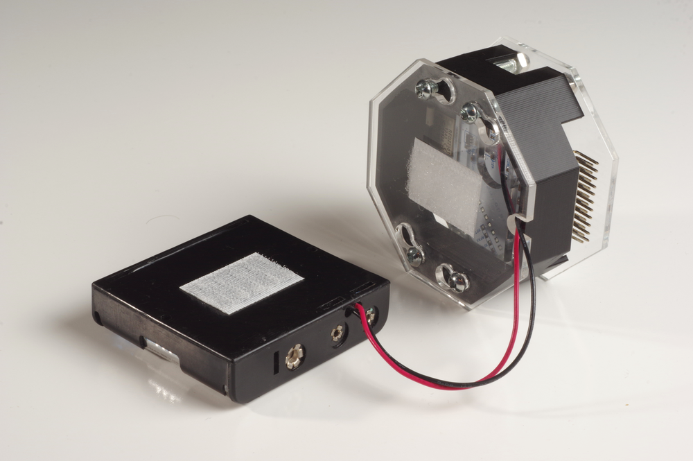
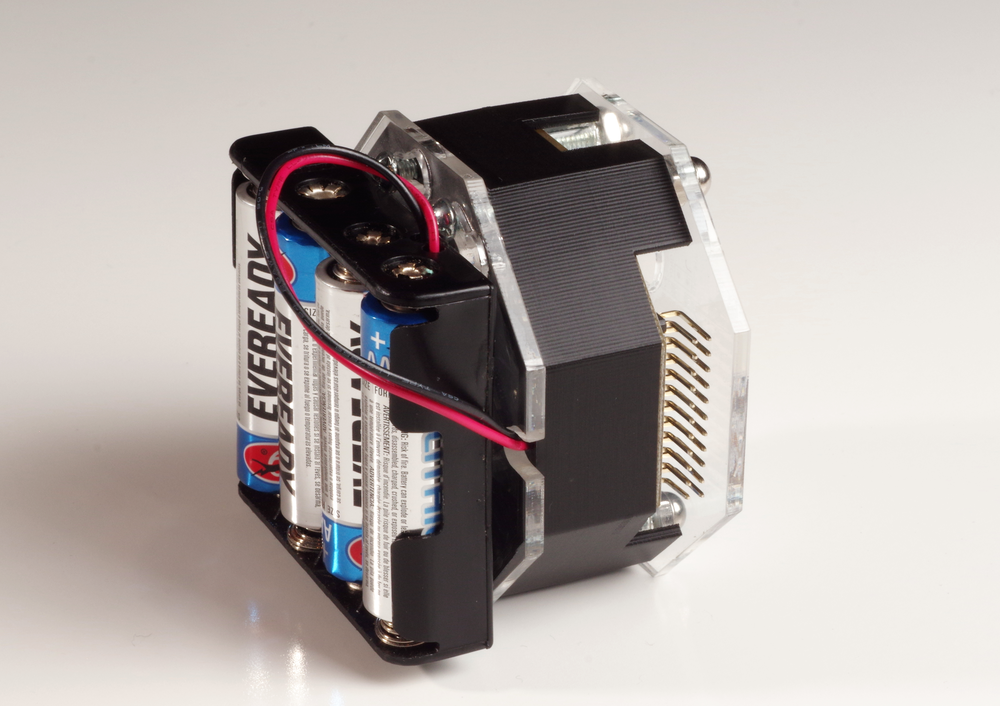
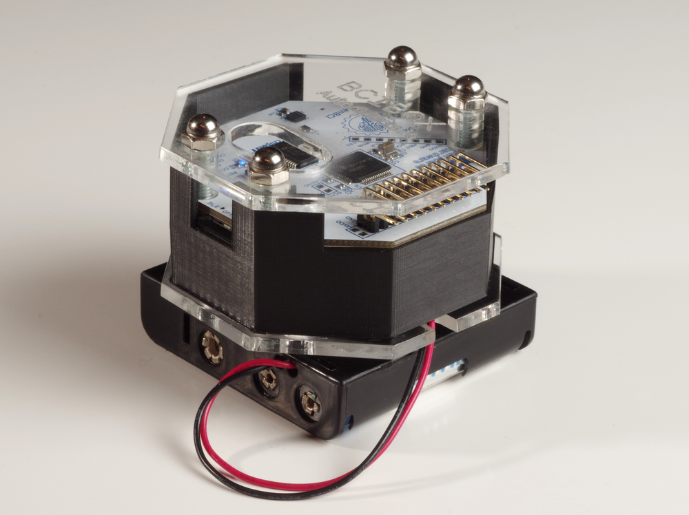
To use the AA pack, pop off the BCIBox’s bottom cover and plug your battery pack’s JST connector into the socket on the bottom of the OpenBCI board. (The connector has to be in line with the socket before it will go in. Use a pair of needle-nosed pliers or a pencil to get it lined up if necessary.) Put the bottom cover back on, running the power wire through the notch in the edge of the bottom cover. If you’re not using an extender for the battery wire and you want the battery pack to stay with the OpenBCI, you can use some adhesive-backed velcro (supplied with the kit) to attach the battery pack to the bottom of the BCIBox. This will keep it in place while still allowing you to remove the pack as needed.
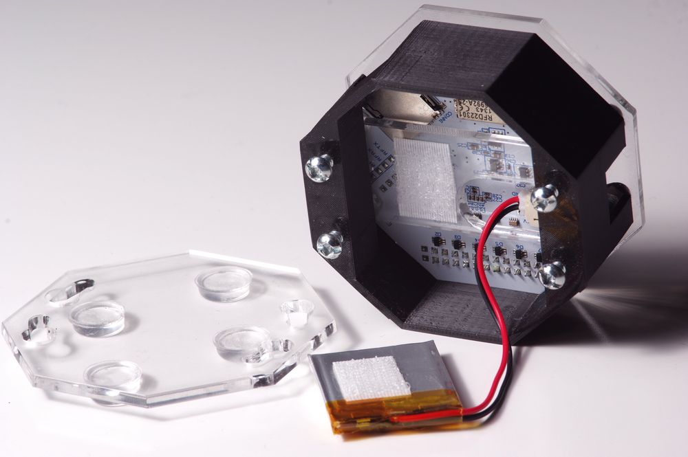
If you’re using a lipo battery (we’ve found this inexpensive 3.7v one-cell lipo from Adafruit works quite well for the 32-bit board), attach one side of a piece of adhesive-backed velcro to the battery support acrylic in the BCIBox, and the other side to your lipo. Plug the lipo into the OpenBCI, connect the velcro, and snap the bottom cover back onto the BCIBox.
For 8-bit boards that don’t run on a one-cell lipo directly, you can use a boost converter to increase the output voltage from the lipo. Aside from boosting the voltage to power the 8-bit board, the boost converter also works as a USB charger for the lipo. Both the boost converter and the lipo fit into the box. We recommend attaching the converter and battery to each other using elastic bands, velcro, or adhesive tape, and then velcroing them into the box as with the lipo above.
Rubber feet
If you’re not attaching an AA pack to the bottom of the BCIBox, you’ll want to add some rubber feet. These prevent the screws from scratching any sensitive surfaces, and help keep the box from sliding around. The kit comes with four rubber feet. Pull them off of their backing, and stick them onto the bottom panel, as far apart from each other as possible without obstructing the screw holes.
Holding the BCI-In-A-Box
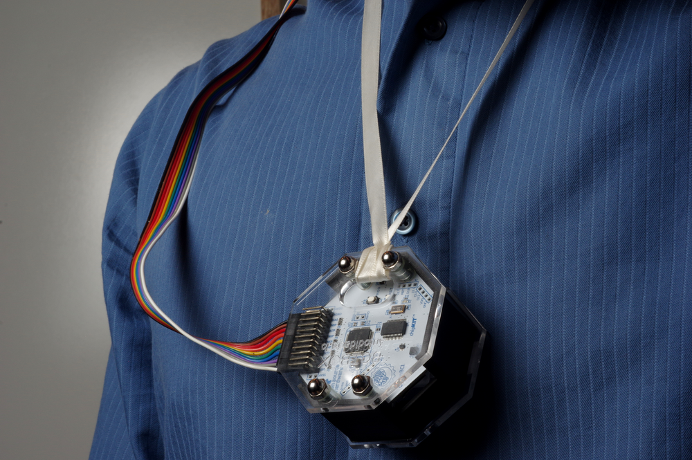
We wanted to make the OpenBCI as user-friendly as possible with this box. Here are a couple of tips for holding the box and BCI close to your head for best results:
-
Pocket The simplest way to keep track of your BCI when it’s in use and enclosed in a BCIBox is to pop it into a breast pocket.
-
Lanyard attachment If you don’t have a suitable pocket, you can attach a lanyard to the BCIBox that will allow you to hang the BCI around your neck. To do this, we recommend tying a piece of thin ribbon or string into a loop. Put one end of the loop in through the switch port in the side of box, then up and out through the button access hole in the top panel. Run one end of the loop through the other end and tighten it up so that you’ve tied a “cow hitch” around the edge of the top panel. Put the ribbon over your head (of course, this is best done before your head has electrodes on it!).
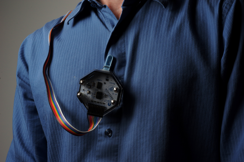
- Lapel clip Another technique for securing the BCI is to use a piece of adhesive-backed velcro to attach the box to a clothes peg (supplied with the kit). Cut a short slice of velcro, peel off the backing and stick the velcro to the clothes peg and the bottom of the BCIBox. Clip the peg to your shirt collar or, in the case of a button-down shirt, to the front of the shirt between two buttons. This can also be used to attach the BCIBox to an armband.
Conclusion
We hope the BCIBox will make the wonderful technology of the OpenBCI even more accessible for neuroenthusiasts, researchers, and tinkerers!
If you haven’t already, head over to the BCIBox GitHub repo to grab the manufacturing files, or order the ready-to-assemble kit for $35 USD by clicking this unsightly orange Paypal button:
Note: we’re working on v2 of the BCIBox, and are not taking new orders for v1 boxes. If you’d like to preorder our next version, send us an email at info@autodidacts.io
If you have any questions about the build, suggestions about how we should improve the design in the future, or just want to share a photo of your enclosure, leave a comment below, send us and email, track us down on twitter, or open an issue on the BCIBox GitHub project.
Thanks for reading!
The first BCIBox version had some issues accommodating the taller headers and slightly different power port location on the Ganglion. This has been fixed in more recent versions, though the photos in this article still show the original version. ↩︎